
Maintenance
There are multitudinous subjects to be covered in Maintenance. The table below will give you a good idea of the times, etc., at which you should conduct maintenance. These parameters are good guidelines for the initiation of a 300-Hour Inspection, which may be seen below.
Critical Engine Parameters
- Calendar time: 5 years
- Time since Overhaul or IRAN: 1500 hours (D Model) 2000 hours (E Model)
- Over Temp Start or in Operation
- Over Speed
- Hard Landing: IRAN is recommended
- Exceeding 3.8 G's
- Prop Strike: Probably an IRAN is called for
- FOD in compressor
- Failure to pass a Borescope Inspection (below)
- Over Torque more than 10% over Max
- 2250 cycles
Inspections
300-Hour Inspection
- Perform borescope inspection of compressor turbine, compressor turbine nozzle, inner combustion chamber, first stage compressor and power turbine.
- Check front and rear chip detectors.
- Drain and replace engine oil.
- Remove and sonic clean oil filter.
- Clean magnet on oil drain.
- Check spark plugs, spark plug wires, and spark plug regulators.
- Test left and right ignitors.
- Check engine for oil leaks.
- Clean propeller governor and lubricate cable, joints and slides.
- Check beta block, propeller bolts, and propeller for corrosion.
- Check propeller clamps, spinner and bolts.
- Remove propeller blades from hub and check for corrosion.
- Remove starter generator.
- Remove starter generator brushes and check.
- Spin commutator and check bearings.
- Check and clean spline.
- Copper slip spline and fit.
- Do general inspection of all nuts and bolts, locking wire, engine mounts, cables, connections, oil leaks and electrics.
- The Fuel filter must be at least 10 micron or better.
- Clean Fuel Control Unit and lubricate the joints and slides.
- Bleed Fuel Control Unit.
- Check the blow-off valve, and if necessary, remove and clean.
- Start turbine and check parameters through the first and second stages of start.
- Check the isolating valve.
- Fuel pressure should be a minimum of 14 PSi & a Maximum of 49 PSI (Preferred 28 PSI).
- Oil pressure needs to be a minimum of 30 & a maximum of 39.
- N1 at idle should be a minimum of 60% and a maximum 65%.
- Voltage during start needs to be a minimum 20 volts.
- Check the charging of the generator.
- Check ITT at idle 480 to 520 +-.
- Check after shut down for irregular bearing noise from compressor and power turbine.
- Check for cracks on exhausts.
- Check drains on fuel pump, FCU, hot section and EPA can.
- Perform engine spectrum analysis.
- Finally, Balance the propeller.
100-Hour Inspection
Note: Perform the 100-hour inspection 100 hours after an IRAN. Thereafter, annually or each 300 hours, perform the 300-hour inspection (which see).- Perform borescope inspection (which see) of compressor turbine, compressor turbine nozzle, inner combustion chamber, first stage compressor and power turbine.
- Check spark plugs, spark plug wires, and spark plug regulators.
- Test Left and Right ignitors.
- Check for oil leaks.
- Clean prop governor and lubricate cable, joints, and slides.
- Check beta block.
- Check spinner, prop bolts, and prop clamps.
- Check for corrosion on the propeller.
- Do general inspection of all nuts and bolts, locking wire, engine mounts, cables, connections, oil leaks and electrical connections.
- The fuel filter must be at least 10 micron or better.
- Clean the fuel control unit and lubricate the joints and slides.
- Bleed the Fuel Control Unit.
- Check isolating valve.
- Check the blow-off valve. If necessary, remove and clean.
- Start turbine engine and check parameters through first and second stage of start.
- Check fuel pressure - needs to be between a minimum of 14 PSI,& Max 49 PSI (Preferred 28 PSI.)
- Check oil pressure - needs to be between a minimum of 30, max 39.
- Check N1 at idle - needs to be between a min 60%, & max 65%.
- Check voltage during start. Must be a minimum of 20 volts.
- Check charging of the generator.
- Check ITT at idle 480 to 520 + -.
- Check after shut down for irregular bearing noise from compressor and power turbine.
- Check for cracks on exhausts.
- Check the drains on fuel pump, FCU, hot section and EPA can.
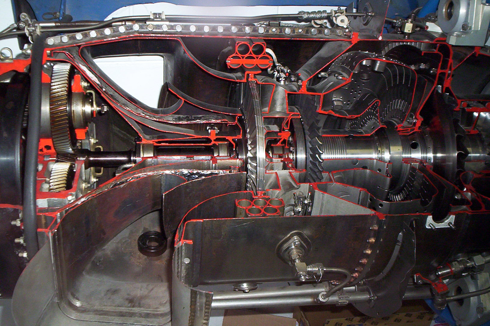
Borescope Inspections
First Stage Compressor
Remove intake screen, insert borescope or mirror to examine first stage compressor blades for damage, including heat damage.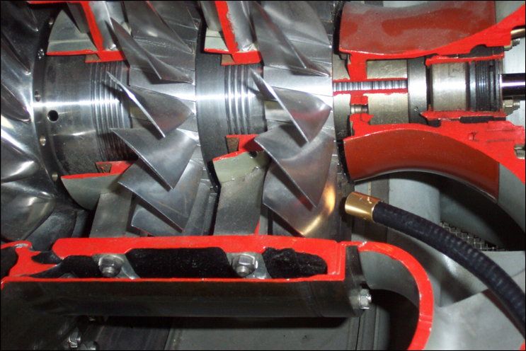
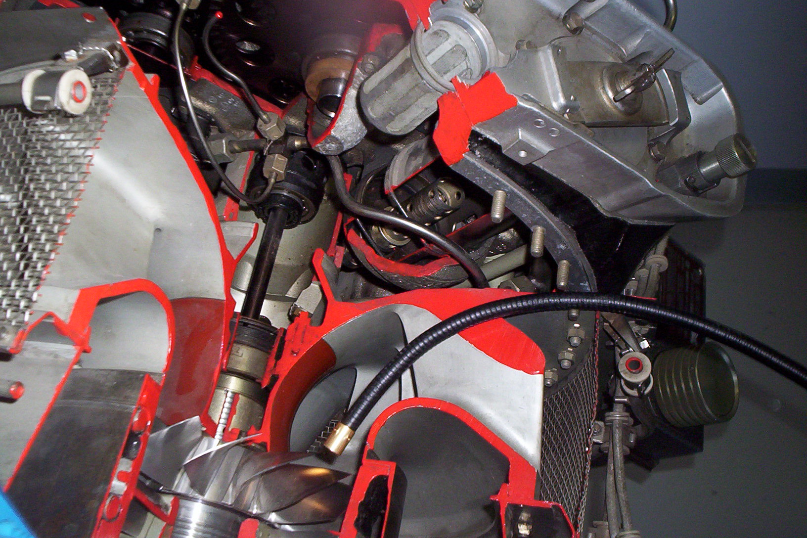
Inner Combustion
Remove both torches and injector tube. Check tubes for cracks, insert borescope, examine inner combustion chamber for cracks or heat damage.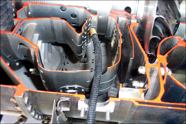
Strator
After examining inner combustion chamber, then examine compressor turbine wheel stator for cracks or heat damage.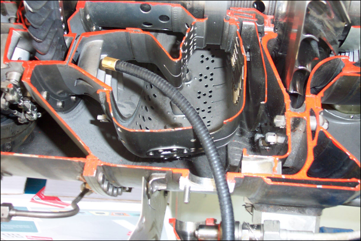
Compressor Turbine Wheel
After examining compressor turbine wheel stator, insert borescope between stator blades to examine compressor turbine wheel blades. After inspection replace torches and gaskets as necessary.
Power Turbine Wheel
Insert borescope through exhaust and examine power turbine wheel blades.Power Turbine Wheel:
Damaged Borescopes
 |
Impact damage compressor blades (045) |  |
Impact damage compressor blades (045) |
 |
Impact damage to comp turb (020) |  |
Post-heat damage to compressor turbine (019) |
 |
Power turbine blades (001) |  |
Damaged power turbine blades (000) |
 |
Inner combustion chamber heat damage (004) | |
Damaged power turbine blades (000) |
|
Inner combustion chamber heat damage (004) |  |
Inner combustion chamber Note Crack (003) |
 |
Inner combustion chamber heat damage (002) |  |
Inner combustion chamber heat damage (001) |
 |
Bad crack at top of Inr Cmbst,chbr (000) | |
Bad crack at top of Inr Cmbst,chbr (000) |
|
Inner combustion chamber heat damage (001) | |
Bad crack at top of Inner Combustion chamber |
 |
Compressor turbine stator (nozzle) front (007) | ||
Operations and Limitations
This is not to be used as a check list. This is only to be used as a guide to start the Walter M601 B, D & E Turbines.
AUTO START (Limiter):
- Power on.
- Inverter on if necessary.
- Fuel on.
- Fuel pump/pumps on.
- Condition lever forward to detent.
- Propeller in feather position.
- Throttle in idle position.
- Press start. It is best to keep a hand on the condition lever in case of overtemp.
- Carefully monitor the ITT for increasing temp, do not exceed 710 degrees. Rate of increase is important. If over temp occurs, pull the condition lever to the shut-off position.
- Make sure N1 (Compressor rpm) increases to at least 60%. If not, forward throttle slightly and monitor ITT.
- After N1 and ITT stabilize, switch on generator.
- Check oil and fuel pressure.
- Advance the prop to full-fine pitch.
Auto Start With Push Button (EHT):
- Fuel On
- Power on.
- Fuel pump on.
- Throttle to Idle.
- Prop to Feather.
- Condition Lever to Run position.
- Press Start, keeping a hand on the fuel condition lever, and be ready to cut the fuel in case of over temp.
- As the turbine lights, press the EHT button +- two seconds and carefully monitor the ITT. When the ITT slows down or tends to stabilize, release the button to increase the ITT and N1. Repeat this by keeping the ITT between 580°C and 650°C. The further into the start, the more abrupt and sensitive the EHT will become.
- Make sure N1 (Compressor RPM) increases to at least 60%. If not, advance the throttle slightly and monitor the ITT.
- After N1 and ITT have stabilized, switch the generator on.
- Check oil and fuel pressure.
- Advance the Prop to full-fine pitch.
Recommended Practices: It is good practice to start the turbine with headsets off. A possible over temp can be heard quicker than the ITT gauge can display it.
CAUTION: Keep one hand on the Condition Lever and be ready to cut as the button will not prevent an over temp if the throttle is partly open, the batteries are low, or there is high outside temperature and / or elevation. If there is a high turbine temperature (over 150°C) before starting, a wind from the rear, a blockage of the air intakes, or the ISOL valve is in the ISOL mode, these may also cause an over temp.
Important Notice: If the ITT exceeds 735°C and no more than 800°C, the turbine must be inspected for damage (Borescope). If ITT exceeds 800°C, the turbine must be dismantled for inspection and a possible change of all compressor turbine blades. To continue operation after an over temp could cause a catastrophic failure!
Cold Cycle (motor):
- Master switch on
- Fuel on
- Fuel pump ON
- Throttle to idle
- Prop to Feather
- Condition lever in shut off position
- Turn the Motor switch on and carefully monitor the 20-second Motor sequence.
NOTE: If aircraft batteries are used during the Cold Cycle without a GPU, it is possible to worsen the problem by depleting the batteries. It is possible to cold cycle the turbine for five to eight seconds and abort by switching the Master off. This will save the battery power and should reduce the turbine temperature enough for a successful start.
IF THE TURBINE TENDS TO OVER TEMP DURING START, THE PROBLEMS COULD BE:
- The Batteries have insufficient power.
- The limiter is not working (electrical).
- Throttle linkage adjustment is incorrect - FCU lever has to be on "0" degrees.
- An adjustment is needed on the FCU.
- High elevation.
- High outside temp.
- Strong wind from rear of aircraft. Turn into wind.
- If ITT is 150°C and over, cold cycle (Motor) the turbine to cool it off before attempting a start.
Manual Start:
- Power on.
- Inverter on if necessary.
- Fuel on.
- Fuel pump / pumps on.
- Condition lever in shut-off position.
- Prop in feather position.
- Throttle in idle position.
- ISOL valve on (emergency throttle system).
- Press start.
- Monitor N1 (compressor rpm). When N1 reaches 16 / 18%, feed fuel in by forwarding condition lever, it could be necessary to forward almost to indent position to light. Once turbine has lit, reduce fuel by pulling condition lever towards shut off position not to exceed 620 / 680. Keep adding fuel by forwarding condition lever until such time as the N1 reaches 60 / 63 %.
- At 60 / 63 % N1 make sure throttle is in idle position and switch ISOL off (normal position).
- Monitor oil pressure, fuel pressure, ITT, N1 and torque.
- Generator on.
- Forward prop lever to full-fine pitch.
Note: If starter generator is fitted with the standard timer LUN 2601-01, it will engage for 20 seconds. It is necessary to try to achieve 60 / 63 % N1 before starter disengages to minimize an over temp. At anytime, if there is a possibility or over temp, pull the condition lever to a shut-off position.
It is also important to achieve 60 / 63 % N1 before switching ISOL valve off. A slight bump/burp (compressor stall) will be heard, this is normal. The lower the N1 is to 60 / 63 % the more abrupt the change over from ISOL to normal mode will be.
TAXIING: Taxiing can be done in beta range or feather. When taxiing in feather with low clearance propellers, the propeller blades tend to sweep the taxiway lifting dirt and stones into the air intake.
TAKE OFF: Make sure the prop has come out of beta range and stabilized before adding power. (Adding power whilst the transition is taking place from beta to normal mode will result in an over speed of the prop stretching the blades on the power turbine wheel leading to possible failure.)
Add power gently to achieve the necessary take off power. Monitor the ITT, N1, N2 and torque.
Max ITT take off on calibrated Czech gauges 8 OHM 710C. It has been found that some American gauges read low by as much as 50 °C.
-
MAX Take-off power 1 minute:
- ITT: 710Max
- Max N2/Np: 2080 rpm
- Max torque: 105% +- 132 PSI if using oil pressure gauge
-
MAX Continuous:
- ITT 690
- N1/Ng 98.2%
- N2/Np 1850 - 2080 rpm
- Torque 100% +/- 128 PSI
-
TYPICAL CRUISE Power Setting:
- ITT 660
- N1/Ng 97.5
- N2/Np 1700 - 1850 rpm
- Torque 90%
-
MAX REVERSE Thrust:
- ITT 710
- N1/Ng 99%
- N2/Np 2000 rpm
NEVER use reverse thrust in flight!
SHUT DOWN:
- Throttle idle.
- Allow propeller to feather for 60 seconds.
- Turn electrics off except for the inverter and battery.
- Condition lever to shut off position.
- Turn inverter and master off. (A good time to check engine oil is soon after shut down.)
WHEN AND HOW TO USE THE ISOLATING VALVE (ISOL/ EMERGENCY CIRCUIT) IN FLIGHT:
In flight, if a reduction in torque and an increasing ITT occurs, the probable cause would be mechanical. The ISOL will not work and we suggest you land the plane soon.
If a reduction in torque, N1, and/or ITT occurs and adding of power does not make a change, there is a probable problem with the FCU (Fuel Control Unit). Reduce power to idle (throttle) and make sure the condition lever is in the indent position +/- 1/3 forward. Select ISOL valve and use condition lever as throttle.
To come out of ISOL, make sure the throttle is in idle position. Bring condition lever to the indent position +/- 1/3 forward and select off on the ISOL valve switch. The throttle can now be forwarded to the necessary power setting.
STARTING LIMITATIONS
- Minimum ambient air temperature for starting engines without their preheating is -20°C
- Maximum inter-turbine temperature during starting from an external power source 700°C
- Maximum inter-turbine temperature during starting from aircraft batteries 735°C
- Minimum generator speed after spin up of the engine by the starter 18 %
- Maximum altitude for engine restarting in flight 13,000 ft
- Maximum number of engine starting (turning) attempts from an external power source following at 3 minute intervals
- The next attempt can be made after one hour.
- Voltage of external power source during starting (no load) 20 to 31 Volts.
- Allowable voltage drop of aircraft power supply during the initial phase of starting (not over 4 seconds) min. 14 V
- Maximum number of starts attempts from aircraft batteries (3 minute intervals)
FUEL SYSTEM
- Maximum flight altitude in case of all fuel pumps failure 13,000 ft.
OIL SYSTEM
The engine can be lubricated exclusively with the following oils:- Aeroshell Turbine Oil 500
- Aeroshell Turbine Oil 555
- Aeroshell Turbine Oil 560
- Mobil Jet Oil 11
- BP Turbo Oil 2380
- Castrol 599
MISC. OIL SPECIFICATIONS
- Minimum oil quantity in engine 5.5 L
- Maximum oil quantity in engine 7 L
- Minimum oil temperature during starting: 120 °C
- Maximum oil temperature for engine acceleration and normal engine operation: 850 °C
- Minimum oil temperature for engine acceleration and normal engine operation: 200 °C
- Maximum oil consumption 0.1 L / h
- Minimum permissible oil pressure: N1/Ng 60% (17 PSI) 0.12 MPa (1.2 kp/cm2)
- N1/Ng 80-101.5% (26 PSI) 0.18 MPa (1.8 kp/cm2)
- Maximum permissible oil pressure (39 PSI) 0.27 MPa (2.7 kp/cm2)
Note: For oil temperatures range 20-550 C oil pressure can be higher by 43 PSI (0.03 MPa) (0.3 kp/cm2). Increase of oil pressure to a maximum of 50 PSI (0.35 MPa) (0.3 kp/cm2) is permitted for a short time during starting at temperatures below 0 °C.
Short-term oil pressure drop to zero 10 seconds.
OTHER ENGINE LIMITATIONS IMPOSED BY THE POWER PLANT
Bleed Air for aircraft systems: Air bleed ducts must not be opened with the engine operating at maximum take-off power or at emergency power. With air bleed on the gas temperature (ITT) will rise by approximately 30 °C. It is therefore necessary to set the engine operating parameters after the bleed air has been opened so that the maximum inter turbine temperature (ITT) shall not be exceeded.
Use of reverse thrust: Reverse thrust may only be used during landing after touch-down. It is forbidden to use beta or reverse thrust in flight.
ELECTRIC SYSTEM
- Electric power sources: Normal voltage in DC system: 27 to 29.0 V
- Maximum load of generator in flight: 200 A
- Maximum load of generator on ground (30 min maximum): 100 A
BLEED FUEL CONTROL UNITS (FCUs)
There are four bleed ports on the FCU; bottom left and right, one located at the back, and the other on top.
It is important for the electrical fuel pump to run continuously during the entire bleed process. It must not be turned off during changing of the bleed pipe.
- Remove all four bleed caps.
- Condition lever to shut off position, throttle to idle.
- Turn electrical fuel pump on.
- Fit fuel bleed pipe to bottom port till no air can be observed, continue bleeding from the bottom ports up to the last one located all the way on top.
- Fit bleed caps and start Turbine.
If the FCU or fuel filter has been replaced, repeat the procedure again after the Turbine has been run. A quick check can be performed by switching the electrical fuel pump off while idling on the ground, if the Compressor RPM ( N1 ) drops off more than 5%, bleed the FCU again.
For technicians that do not have the bleed fitting with pipe, a small Allen wrench ( Hex Key ) or .041 locking wire can be used carefully to activate the Schrader valves in situated underneath the bleed caps. If the FCU has been replaced, ensure all throttle and condition lever settings are correct before attempting a start.